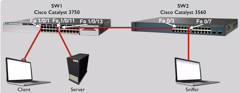
SPAN or Switched Port Analyzer, tells the switch to send a copy of frames out of another switch port. This is usually used for traffic sniffers (Wireshark for example).
To set this up:
SW1(config)#monitor session 1 source int fa 1/0/1 (This is the switch port that we want to monitor)
SW1(config)#monitor session 1 dest int fa 1/0/12 (This is where the copy of the frames will be sent)
Along with monitoring a single interface, we can also monitor an entire VLAN’s traffic.
SW1#show monitor
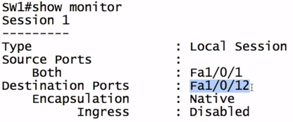
RSPAN
RSPAN (Remote Switched Port Analyzer) is the same as SPAN, only it gives you the ability to have the copied frames sent to a port that is not on the local switch.
With RSPAN, you need to create a VLAN that will be used to carry the copied frames.
SW1(config)#vlan 50
SW1(config-if)#name RSPAN
SW1(config-if)#remote-span
SW1(config-if)#exit
Now that we have a VLAN created for RSPAN, this can be used as a destination to send the copied frames too.
SW1(config)#monitor session 2 source int fa 1/0/1
SW1(config)#monitor sessions 2 dest remote vlan 50
Now we need to set this up on the remote switch. Ensure that the vlan exists on the remote switch.
SW2(config)#monitor sessions 3 source remote vlan 50
SW2(config)#monitor session 3 dest int fa 0/7


